Multi-scale,nature,of,non-blade-order,propagating,flow,disturbances,in,axial,compressors
来源:优秀文章 发布时间:2022-11-11 点击:
Hao WANG, Yan’gang WANG, Hanru LIU,*, Fei XUE, Zhongnan WANG
1 School of Power and Energy, Northwestern Polytechnical University, Xi’an 710072, China
2 College of Engineering and Physical Sciences, University of Birmingham, Birmingham B15 2TT, United Kingdom
KEYWORDS Axial compressors;Flow instabilities;Multi-scale disturbances;Stall;Unsteady flow
Abstract Non-blade-order flow disturbances, also referred to as pre-stall disturbances or tip flow unsteadiness,are closely related with compressor instabilities.The present work provides a comprehensive investigation on multi-scale nature of non-blade-order disturbances and the underlying flow physics in axial compressors.By applying full-annulus Unsteady Reynolds-Averaged Navier-Stokes(URANS)simulations,along with space–time correlation and spatial Fourier decomposition,to the disturbed pressure, the propagating feature of the non-blade-order disturbances is obtained. Further,a bridge between non-blade-order disturbances and the evolution of unsteady vortex has been set up.The results show that non-blade-order disturbances,featured as short-length-scale(35 modes across annulus),first appear as the occurrence of tip leakage vortex fluctuation,while the compressor still operates far from stall. Leading-edge radial vortex appears at near stall condition, and its movement induces a circumferential propagating disturbance overlaying on the one induced by oscillating tip leakage vortex. The interaction of the short-scale disturbances with a lowamplitude long-scale (of circumference)disturbance is observed, which results in disturbances with multiple scales of consecutive spatial modes, along with multiple frequency peaks in spectra. The compressor falls into stall as the circumferential nonuniform scattering of the leading-edge vortexes occurs. The densely- and sparsely-scattered leading-edge radial vortexes induce a high-amplitude long-scale (of circumference) disturbance, i.e. stall disturbance.
As one kind of rotary-type turbomachinery, compressors take advantage of the rotation of the impeller to work on the through-flow gas and to improve its pressure and kinetic energy. With a certain number of blades installed uniformly on the impeller, identical rotor blade passages circumferentially distributed around the annulus guide the gas flow and whirl it outward, thereby increasing the angular momentum of the fluid, together with its pressure and velocity. Due to the complex geometric configuration and rotating nature of compressors, the inherent flow field is highly unsteady and comprises flow disturbances covering a wide range of time and space scales.
When compressors operate under stable conditions, the steady loading of rotor blade generates a pressure profile from blade to blade, seen from the absolute coordinate frame, the rotation of which introduces a periodical fluctuating wave circumferential propagating around the annulus. This periodical fluctuating wave induced by the rotation of the steady blade loading has a circumferential periodicity (or mode order) of the blade number and a frequency of Blade Passing Frequency(BPF),which can be named by Blade-Order flow Disturbances(BOD).If considering rotor–stator interaction or non-uniform incoming flow,some extra flow disturbances(or called interaction modes) are introduced by the interaction between the rotating blade loading and the flow profile of stator or nonuniform inflow. Though the mode order of the interaction mode is not necessarily equal to the rotor blade number, it is physically originated from the rotating blade loading and can be derived by a simple algebraic relation between rotor number and stator number (or circumferential periodicity of the non-uniform incoming flow). Further, the frequency of the interaction modes is also fixed on the BPF, and thus they can be ranged into BOD as well. The blade-order flow disturbances can be well explained and described by the established turbomachinery theoretical system, as Tyler and Sofrin’swork on rotating acoustic modes in axial compressors. However, as the compressors develop with higher performance and stability, along with more and more in-depth study on the turbomachinery aerodynamics, another kind of flow disturbance—Non-Blade-Order flow Disturbances (NBOD)(with mode order not on rotor blade number and frequency not on BPF)—have come into the sight of the related engineers and researchers, the importance of which is reflected by its close relation with the compressor instabilities, including both aerodynamic and aeromechanical instabilities.
A very typical kind of non-blade-order flow disturbance is the disturbances caused by stall cells, which occurs under the post-stall operation condition of compressors.The periodicity of the rotating stall disturbances in one annulus depends on the stall cell number. Another typical kind of non-bladeorder flow disturbance is the stall inception disturbance which has been studied extensively,because it is an important precursor signal indicating the imminent stall or surge.Previous extensive studies have shown that the stall inception disturbance can be divided into two categories: the modal disturbance and the spike disturbance.The modal stall disturbance is featured as low-amplitude large-scale disturbances with wavelength of rotor circumference, which initially experiences 10 to 100 revolutions of rotor before stall onset.The spike stall disturbance has much smaller length-scale(one to several blade pitches) and higher amplitude. In case of the occurrence of the spike disturbances, the compressor will fall into stall in only 3 to 4 revolutions.Though the length-scale of the modal and spike disturbances are different,seen from the perspective of compressor annulus,their periodicity across one annulus are both 1.
Since this century, another kind of non-blade-order flow disturbance enters the view of turbomachinery researchers,named pre-stall disturbance,the circumferential mode order(wave number of periodicity across one annulus) of which is usually not confined to the blade number.Pre-stall disturbance attracts the researchers because it is not only a potential stall indicator for developing stall warning systems, but also a possible source for triggering blade vibration or intensifying aeroacoustic noise. Due to the ambiguous knowledge into the physics and non-unified definitions by researchers in this domain, the subject of pre-stall disturbance has a crossrelation with the subjects of rotating instability and tip flow unsteadiness.However,from the perspective of physical nature and characteristics, the term of non-blade-order flow disturbances can cover the contents of the above three subjects.Through experimental investigations, Inoue et al.observed that the length-scale of stall inception disturbances converted from short-scale to long-scale when reducing the tip gap, and proposed the hypothesis that the short-scale disturbance was induced by a vortex separated from blade surface to reduce circulation. For exploring the flow physics of rotating instabilities, Marz et al.carried out both experimental and numerical investigations, and found that the circumferential migration of a radial vortical structure was the cause of the propagating disturbances.Based on a four-stage research compressor, Mailach et al.applied time-resolving pressure measurements in both stationary and rotating coordinate of reference to achieve a detailed description of the spatial development of circumferential flow structure, and considered that the periodical interaction of tip gap vortex of one passage with the flow in the neighboring passage led to a short-length-scale rotating flow structure, named rotating instability. Through unsteady pressure measurements in a transonic compressor,Biela et al.found that the oscillations of the tip leakage vortex resulted in an excited frequency band at around half the BPF,and further the appearance of rotating tip vortex disturbances induced a double-passage periodical vortical pattern.Hah et al.investigated the flow instability in the tip region of a transonic compressor using Particle Image Velocimetry(PIV), casing-installed dynamic pressure sensors and Large Eddy Simulation (LES). They found that two kinds of disturbances with different length-scale coexisted under near stall condition—the low frequency disturbance was induced by a large blockage over several passages, while the high frequency disturbance was due to the movement of the instability vortex.Du et al.numerically observed the self-induced unsteadiness of tip leakage flow in a transonic fan rotor and suggested that it was originated from the interference between tip gap vortex and blade loading. Different from the perspective of vortical unsteadiness, Pardowitz et al.proposed an alternative opinion—shear layer instability by means of elaborate measurements and transient modal analysis techniques, and they suggested that circumferentially propagating disturbances with different wavelengths occurred randomly in the shear layer induced by strong backward flow. Wang et al.investigated the circumferentially propagating disturbances induced by unsteady oscillation of tip clearance vortex experimentally and numerically. They introduced the parameter of phase lag to explain the propagation mechanism and established a theoretical model to quantitively describe the multi-scale propagating disturbances mathematically. By phase-locked PIV,Brandstetter et al.experimentally observed radial vortices traveling circumferentially near blade leading-edge in a highspeed compressor prior to stall, and further demonstrated its correlation with blade vibration. By complementary experiments and numerical simulations, Eck et al.observed a superposition of stall cells and flow disturbances beyond the stalling limit, and therefore considered that the term ‘‘prestall disturbances” does not fit to this phenomenon precisely.Further, they pointed out that the pressure fluctuation caused by pre-stall disturbances was a potential indicator for priorly diagnosing stall and quantifying the deterioration of the clearance height during the lifetime of an engine.
Although, up to now, the term ‘‘non-blade-order flow disturbances”has never been referred to,the existing studies have shown its feature of multiple scales with mode order not confined by the blade number. Further, according to the previous extensive investigations, NBOD is not only closely related to the pre-stall behavior, but also contributes to the stalling process of compressors.Due to the complicated unsteady vortical nature and propagation characteristics behind this phenomenon, the thorough explanation and consensus with respect to its original mechanism and its influence on compressor flow instabilities have not been achieved yet.While most of the abovementioned work looked at the narrow operating range near the stall limit, the non-blade-order flow disturbances can well exist, covering a wider flow range before stall.A comprehensive research, with a development perspective from the initial occurrence to stall condition, on its multiscale propagation characteristics and the related unsteady vortex evolution would be valuable for establishing the relevant knowledge and theory.
Therefore,in current work,a well-tested research compressor has been adopted to investigate the multi-scale nature of non-blade-order flow disturbances and the underlying flow physics. By applying full-annulus transient simulations,together with the effective data processing technique like space–time correlation and spatial Fourier decomposition,the variation of the propagation features of non-blade-order flow disturbances and the associated evolution of unsteady vortical structures along the compressor speed line have been investigated in details. A linkage between the propagation characteristics of non-blade-order disturbances and certain unsteady flow behavior is expected to be established, which provides a deeper physical understanding on non-blade-order flow disturbances.
A researched axial-type compressor was tested in an open-type wind tunnel rig with 600 mm diameter,as shown in Fig.1.The test rig was equipped with a bell-mouth inlet to uniformize the inflow. The operating condition of the compressor was regulated by varying the position of the throttling cone at the rig outlet. The compressor tested had 21 rotor blades with profile of NACA-65-series,together with 13 Inlet Guide Vanes(IGVs)which locate at approximately 1.1 times rotor blade chord length upstream the rotor.The mass flow rate under the design operating condition was 4.9 kg/s with the rotating velocity of 3000 r/min. The clearance size between rotor tip and casing is 2.2% of the rotor span and 3.1% of rotor tip chord. Additional detailed parameters and aerodynamic data were provided in previous work.
The test facility is a typical setup for measuring the steady performance data for an axial compressor.During the aerodynamic measurements, the performance curve of the compressor along the design speed was mapped out by throttling the compressor from choke condition to stability boundary. To obtain the relevant performance parameters, the pneumatic properties were measured at two aero-stations, Ⅰand Ⅱas shown in Fig.1.The inlet total pressure and total temperature were measured with a Prandtl tube at Station Ⅰclosely downstream the bell-mouth orifice, and at the same time, the entrance static pressure was acquired by eight uniformlydistributed casing pressure holes. The pressure rise capacity was obtained by measuring the outflow condition with a calibrated five-hole traversing along the span direction downstream the rotor. Besides, in order to obtain the characteristics of unsteady flow of the compressor,a chordwise array of Kulite pressure transducers were mounted on the casing to measure the time-variant pressure signal near the rotor tip region. The unsteady measurements were conducted under different typical operating conditions along the speed line.The unsteady data from Kulite were acquired with a sampling frequency of 84 kHz, which is 80 times of BPF.
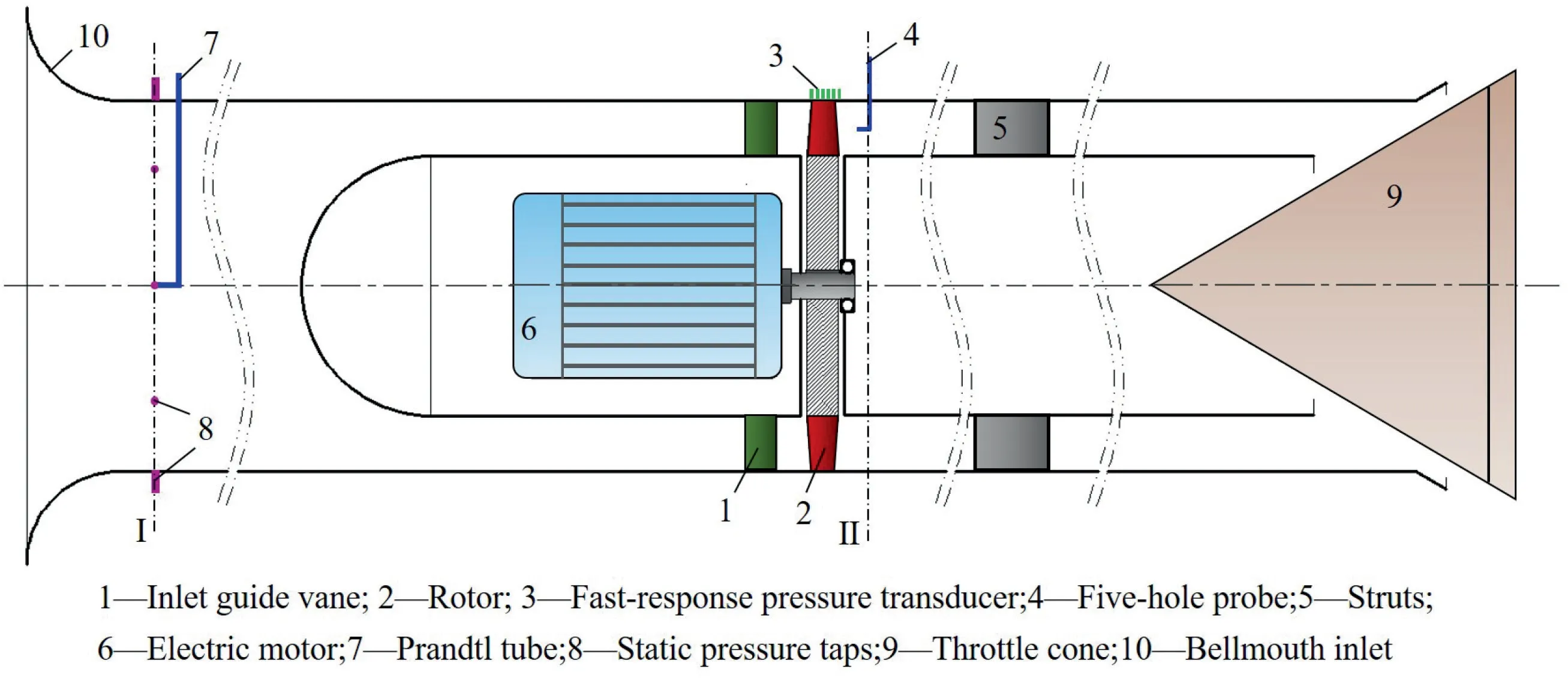
Fig. 1 Schematic of researched compressor rig.
All the steady-state and time-accurate simulations on the compressor flow field were executed by NUMECA/EURANS,which solved the three-dimensional compressible Reynolds-Averaged Navier-Stokes (RANS) equations based on a cellcentered finite volume methodology.The inviscid term was discretized using the second-order upwind approach, while central differential scheme was applied for the viscosity term.Single-equation modeling approach Spalart-Allmaras was adopted to calculate the turbulence. Time marching approach with explicit fourth-order Runge-Kutta scheme was adopted for calculating the steady Navier-Stokes equation. The timeaccurate solutions were simulated with an implicit dual time step approach, and each instant flow solution was seen as a pseudo-steady problem. For the time-accurate calculations, a complete rotation of the compressor was discretized with totally 1344 physical time steps, which is equivalently 64 time steps per rotor blade passing period.
For fully capturing the wide range of the multiple lengthscale flow disturbances circumferentially propagating around the compressor rotor, a computational domain comprising the entire annulus of the rotor was adopted to model the compressor. Since the IGVs were not included in the calculation modeling,the outlet velocity angle was imposed as the domain inlet boundary.The modeling flow domain was axially lengthened to ensure that the distance from inlet and outlet boundary to the rotor was above 1.5 duct radii.With the use of Autogrid V5, the multiple block strategy was applied to generate the structured grid for the flow domain. The mainstream region of the blade passage was modeled with a typical O4H topology, while the clearance zone with H&O grid. The length of the first layer close to the wall was given to guarantee that the normalized wall spacing was less than 3.The independence of the element scale was evaluated with 4 different grid solutions, which respectively comprised 0.45 million, 0.71 million,0.93 million and 1.24 million grids for single blade channel.The chosen solution was the one with 0.93 million grids which achieved mesh independence. This grid solution had 80 elements along the span direction (24 elements in the clearance region), 120 elements along the stream direction and 64 elements in the pitch direction.The mesh for single blade channel was duplicated for 360° to achieve the full-annulus mesh for the compressor rotor, the total element number of which was 19 × 10. Fig. 2 provides a schematic of the computation domain with mesh details.
For the boundary condition, the inlet was prescribed by evenly distributed total temperature and total pressure, along with the radial distribution of inflow angle. The outlet boundary was specified by the average static pressure from the measurements. The other relevant variates at the exit were calculated from the inside flow domain,while the pressure profile was integrated to ensure that the mean value met the specified one. Besides, adiabatic and non-slipping conditions were imposed on blade,hub and shroud surface.To obtain the fluctuating signals in the rotor tip region,three groups of pressure monitor points were adopted during the time-accurate simulations,as shown in Fig.3.The first group(A-A,black dots)was in the relative frame of rotor’s rotation,which covered the whole annulus at the rotor Leading-Edge (LE). The second group (P-P, red dots) was in the relative coordinate associated with the rotating blade passage which distributed from 1/4 chord upstream of the leading-edge to 1/4 chord downstream of the Trailing-Edge (TE) along the chord direction.The third group (S-S, blue dots) was imposed on the casing surface in the absolute stationary coordinate covering the same axial range of the second group, the results of which could be compared with the measured ones.
4.1. Validation of steady and unsteady data
For numerical simulation,both steady and unsteady approach have been, respectively, performed to obtain the compressor flow field under different operating conditions at design speed from the near choke point to the stall limit. The calculated characteristic curve of total pressure rise versus flow rate is shown in Fig. 4, where the nondimensional total pressure rise coefficient ψ and flow rate coefficient φ are formulated by ψ = 2P/(ρU) and φ = 4Q/(πDU), where Pis the total pressure rise, ρ is the air density, Uis the rotor tip velocity,Q is the volume flow rate,Dis the rotor tip diameter.As illustrated in Fig. 4, the unsteady results (green rhombus) match with the experimental data (grey square) very well in most of the flow range except for the near stall range where it shows a little higher total pressure.That can be explained by the fact that the RANS method underestimates the flow loss when compressor operates near stall,because stronger vortex,stronger separation and the associated unsteadiness dominate the compressor flow field under this condition. In addition, the results also depict that the steady data can only predict the total pressure rise accurately in the large flow range(φ >0.168), while it deviates from the measured curve from the condition φ = 0.168. Moreover, the fluctuated pressure data from both numerical and experimental methods (which are discussed and analyzed in details in the following Fig. 5 and Fig.6)show that the condition φ=0.168 is the inception point of the circumferential propagating flow disturbance appearing in the rotor tip region. Therefore, the increased unsteadiness in the rotor tip region may be the reason why steady approach fails to predict the compressor performance.Four representative conditions are chosen to be discussed in details in the following part of the paper, which are Near disturbance Inception(NI)condition,Peak Efficiency(PE)condition, Near Stall (NS) condition and Rotating Stall (RS)condition.

Fig. 2 CFD grids and details of compressor.
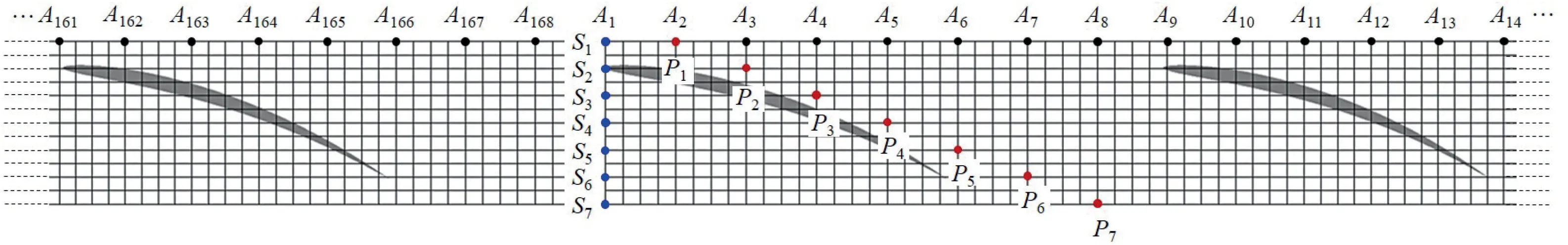
Fig. 3 Schematic of monitor points.

Fig. 4 Aerodynamic performance curve.
In order to ensure that the current numerical approach is capable of capturing the dominant unsteady feature of propagating flow disturbance, the frequency spectra of Sound Pressure Level (SPL) based on the monitored pressure data in the absolute coordinate from the third group have been compared with the measured ones for PE and RS conditions,as shown in Fig. 5. From the spectra, the peaks at BPF (1050 Hz) and its harmonics can be obviously observed, which is the sign of rotating periodic aerodynamic loading of the rotor blade.Additionally,under both PE and RS conditions,a Broadband Frequency hump (named BF) locates below the 1st BPF at around half the BPF, along with the broadband hump BF + BPF which is caused by the modulation between BF and BPF. The broadband humps at BF and BF + BPF indicate the existence of a typical rotating flow disturbance, usually named rotating instability,which generally appears in compressors under near stall condition. The multiple frequency peaks of the broadband hump under PE condition reflect the multi-scale feature of the propagating disturbance.The abbreviation BF is used to express the broadband frequency hump induced by the multi-scale propagating disturbances, and in the following part, it also has the meaning of the center frequency peak of the broadband frequency hump.Besides, under RS conditions, the spectra depict the Stall Frequency (SF) peak at 23 Hz (0.46RF (Rotor Frequency),RF = 50 Hz) for the experimental result and 21 Hz(0.42RF) for the numerical result. The low frequency of the stall peak indicates the long-scale characteristics of the stall disturbances. Overall, the measured spectra and the predicted spectra agree rather well on the major features of the flow disturbances including the frequency value and magnitude of BPFs and stall peaks, as well as the range of the broadband humps of BF and BF + BPF. The capability of the current numerical method to capture the dominate characteristics of flow disturbances has, therefore, been demonstrated.
4.2. Characteristics of fluctuating pressure

Fig. 5 Demonstration of numerical results in frequency domain.

Fig. 6 Monitored pressure trace in relative frame (P2).
The characteristics of fluctuating pressure induced by flow disturbances are analyzed by both the monitored pressure time traces and the associated frequency spectra. Fig. 6 provides the fluctuating pressure traces monitored at the leading-edge of the blade in the relative frame of rotor’s rotation (monitor points in the second group). The pressure value is normalized by the kinetic pressure calculated from the blade tip velocity,and pressure coefficient Cis obtained. This treatment is also adopted in the rest of the paper. It should be noted that the pressure signals in the relative coordinate associated with the rotor’s rotation can exclude the disturbance caused by rotating steady blade loading and bring out the ones induced by flow unsteadiness in the blade passages, like vortex shedding or boundary layer separation. As mentioned above and in Fig. 4, the NI condition is the near inception condition of the flow disturbance that appears. Under the operating conditions with larger flow rate than NI condition, the monitored pressure shows constant value at any position in the rotor flow field, and thus they are not provided in the figure. It can be observed that the pressure signal starts to fluctuate with a relative low amplitude under NI condition, and then its fluctuating level gradually increases as the compressor is throttled to stall boundary.For PE and NS conditions,the pressure signature involves a major component of nearly periodical smallscale disturbance, along with a minor component of longscale disturbance. Under RS condition, prominent lowpressure regions induced by stall cells are clearly seen, which is also supported by the evidence of the significant long-scale feature of the low-pass filtered pressure.
The frequency spectra of monitored pressure signal at Pto Pare provided in Fig.7 for four typical conditions. It is seen that the flow disturbances are reflected in the spectra by a broadband frequency hump at BF and its harmonics 2BF.Under NI condition,the broadband frequency of the flow disturbance is 1331 Hz,equivalently 1.27BPF.As the compressor is throttled,this frequency gradually goes down,which reflects that the time scale of the flow disturbance increases. In addition,the broadband humps under NI and PE condition depict multiple frequency peaks with almost constant frequency interval. Meanwhile, Low-Frequency (marked by LF in Fig. 7)peaks—31 Hz under NI condition and 29 Hz under PE condition, which indicate the existence of a long-scale disturbance,are found to be equal to the frequency interval of the multiple frequency peaks. The multi-peak feature of the broadband hump reflects that the rotor flow field contains disturbances with different time and space scales. And the equality relation of the LF and frequency interval of the broadband hump can be explained by the interaction of a small-scale propagating disturbance with a large-scale propagating disturbance. For NS condition, the LF transfers to higher frequency value 309.1 Hz, thus the multi-peak pattern of the frequency hump disappears, but the BF-LF and BF + LF are still found.Under RS condition, the frequency hump of the flow disturbances depicts a more stochastic broadband nature (446–840 Hz),together with overall improvement of the background noise, which reflects chaotic and random flow disturbances covering a wider range of different time and space lengthscales. Especially, the sharp rise of the amplitude in the low frequency region, under RS condition, indicates the propagation of the stall cells with Stall Frequency (SF = 29 Hz).The constant SPL line (black line) with the same value of Pis also shown in Fig.7 to help compare the level of flow disturbance at different axial positions. It can be found that under NI condition the most intense disturbance locates at the front-half part of the blade passage (P-P). Then as the flow rate decreases,the flow disturbance gradually moves upstream with the most intense location at around leading-edge(P)and upstream of it(P),especially for NS and RS conditions.Furthermore, the low frequency of 309.1 Hz under NS condition and intense stall frequency under RS condition are only found at the location near blade leading-edge, which indicates that some sort of vortex unsteadiness mechanism appears under near stall condition.

Fig. 7 Frequency spectra of monitored pressure in relative frame (P1-P7).

Fig. 8 PLA and RMS pressure on blade-to-blade surface (EXP vs CFD, isolines: PLA, contours: RMS).
The Phase-Locked Average (PLA) pressure coefficient Cand the associated Root-Mean-Square(RMS)pressure coefficient Con the casing surface have been generated by both measured and numerical data, as shown in Fig. 8,which can provide the intensity distribution feature of the fluctuating pressure and correlate it to certain flow pattern.In the figure, the PLA pressure coefficient is depicted by isolines and the RMS pressure coefficient is described by the contours. By the low-pressure trough of the PLA pressure, the trajectory of the Tip Leakage Vortex (TLV) can be obtained, which is drawn by the black dashed line in Fig. 8. Firstly, the trajectories of the TLV acquired by experiments and CFD agree rather well for all the conditions,which further demonstrate the accuracy of the numerical method.It is also observed that the angle between the TLV trajectory and circumferential direction reduces and the TLV original point migrates to the leadingedge,in other words,the TLV moves upstream as the flow rate reduces. From the RMS pressure distribution, it is found that the high RMS region locates upstream and close to the TLV trajectory, which can be explained by the fact that the high fluctuating flow concentrates near the interface of TLV and the main flow rather than the TLV itself. Consequently, the high fluctuating region moves upstream together with TLV as flow rate reduces,which is in accordance with the result of frequency spectra.Additionally,as mentioned earlier,the NI condition is the near-inception point of the flow disturbance appearance. Coincidentally, the TLV trajectory moves to the trailing-edge of the adjacent blade, which indicates that the interaction between TLV and the blade may be the cause of the flow field fluctuation and the disturbance generation.Besides, under the NS and RS conditions, a significant high fluctuating region is observed near the blade leading-edge,which may be caused by the stall cell and will be interpreted in details in the following part.
4.3. Propagation feature of multi-scale disturbances
In order to examine the propagation nature of the multi-scale flow disturbances in the compressor rotor,space–time correlation and Spatial Fourier Decomposition (SFD) techniques have been utilized on the pressure data of the monitored points(A-A)covering the whole annulus.Through the space–time correlation, the time lapse of the circumferential distribution of fluctuating pressure is obtained for all the four typical conditions,as shown in Fig.9.The disturbed pressure coefficient is defined as the instant pressure coefficient at some point being subtracted by the local time-mean pressure coefficient C-C. The circumferential distribution of disturbed pressure can provide the circumferential wave number of the major component of the flow disturbances, and the slope of nearlyconstant pressure track on the time lapse contour can reveal the circumferential propagation velocity of the disturbances.Note that the range of vertical ordinate in Figs. 9(a)-(e) is 0-π(half annulus), while that in Fig. 9(f) is 0-2π(whole annulus).From the Fig. 9(a), under NI condition, the flow disturbance contains 35 wavelengths (periods) across one annulus which is featured as short-length-scale and non-blade-order disturbance, and its circumferential propagation velocity is 1.52π rad/rev(‘‘rev” denotes the time of one rotor revolution), i.e.0.76 Ω(Ωis the rotation velocity of rotor).Through the equation f = N (wavelength number) × Ω (angular velocity), the acquired frequency of the flow disturbance is 1330 Hz for the NI condition,which is in accordance with the result of frequency spectra:the broadband frequency peak of the flow disturbance 1331 Hz(Fig.7).By this approach,the wave number and the circumferential propagating velocity of the major component of flow disturbances under four conditions can be obtained, as annotated in Figs. 9(a)-(d). It is seen that both the wave number and circumferential propagating velocity of the disturbances decrease as the compressor is throttled,corresponding to the reduction of the broadband frequency in the spectra of Fig. 7. The wave number decreases to 30 under PE and NS conditions and 25 under RS condition, while the circumferential velocity reduces to 0.71Ω, 0.6Ω, and 0.51Ωunder PE, NS and RS conditions respectively. Furthermore,the frequencies obtained by the wave number multiplied by circumferential velocity are all in line with the spectral results.Additionally, since the superposition of two kinds of disturbances has been found under RS condition (Fig. 7), the time lapse contour of the circumferential distribution of fluctuating pressure is regenerated by two groups of filtered pressure data.One group is band-pass filtered data(400–800 Hz)covering the broadband frequency hump representing the major component of the flow disturbances,and the other is low-pass filtered data(<100 Hz)to extract the disturbances induced by stall cells.It is shown that the wave number and the circumferential velocity obtained from the band-bass filtered data are the same with those from the non-filtered data,which means that the components of the broadband hump (400–800 Hz) contribute to the major part of the total flow disturbances in the flow field.From the low-pass filtered result, the period of 1 across the whole annulus corresponds to the scale feature of the stall cell,and its propagating velocity is obtained, which is 0.58Ω. In summary, the time lapse of the circumferential distribution of fluctuating pressure shows that the major part of the flow disturbances is characterized by short-length-scale feature for all the 4 typical conditions. However, besides the low-pass filtered data that provide the evidence on the long-length-scale nature of stall cells,the time lapse of the circumferential distribution of fluctuating pressure has not given the information of other gradient of the flow disturbances, especially for those inducing low frequency peak in the spectra(Fig.7).Therefore,SFD based on the spectral data has been performed to examine the multi-scale nature of the flow disturbance related to certain frequency, as discussed in the next paragraph.
The unsteady pressure data from 168 evenly-distributed monitor points covering the whole annulus (A-A) have been used to perform the SFD, the procedure of which is similar as provided by Ref. 16. It should be noted that the SFD herein is carried out on each single frequency, and thus a correlation between frequencies and circumferential wave number(or circumferential spatial modes)can be achieved,as shown in Fig. 10. The total number 168 of the monitor points result in the maximum feasible mode is ±83. Note that the spatial modes of most disturbances are minus, which means that the propagating direction of the disturbances is adverse to the rotating direction of the rotor. From the above spectral analysis, a BF hump with multiple peaks and its harmonics have been found in the monitored pressure spectra, which reflect the multi-scale nature of the propagating flow disturbances around the compressor rotor. Additionally, a LF peak and its harmonics have also been observed in the spectra.By means of SFD, it is found that the main frequency peak of the BF corresponds to 35 spatial modes under NI condition, and 30 spatial modes under PE and NS condition, while the spatial modes of the BF spread from 15 to 30 under RS condition,which are in accordance with the result of the space–time correlation. Additionally, the spatial mode of the LF peak is 1 under NI and PE conditions, which means that it is a disturbance with wavelength of circumference. This long-scale disturbance evolves to spatial mode of 3 under NS condition,and then transforms back to 1 again under RS condition,which indicates the development of the stall cells. Further,for NI and PE conditions,the adjacent peaks of the BF correspond to the spatial modes with consecutive integers, and for NS condition,the difference of spatial mode between adjacent peaks is 3,which is the spatial mode of the LF under this condition. Considering that the frequency interval of the multiple peaks of BF equals the LF at the same time (which is found from the spectral analysis in Fig. 7), the algebraic relation of frequency value f and spatial modes m between BF and LF can be found, which are expressed as

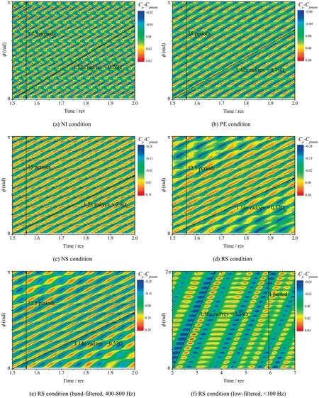
Fig. 9 Circumferential distribution of disturbed pressure Cp-Cpmean with time lapse.

where the subscript MP, BF and LF mean the multiple peaks of broadband hump, the center frequency peak of broadband hump,and the peak of low frequency,respectively.The multiple frequency peaks and the corresponding multiple spatial modes following the above algebraic relation indicate the interaction between the short-scale and long-scale propagating flow disturbances around the compressor rotor.
4.4. Flow physics of multi-scale disturbances
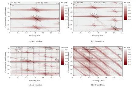
Fig. 10 Spatial Fourier decomposition.
To interpret the physical mechanism of the generation,propagation and evolution of the non-blade-order flow disturbances,the detailed unsteady flow behavior in the rotor tip region is investigated, since the non-blade-order flow disturbances are found to originate from the rotor tip region.The instantaneous λcriterion along with the Cisolines, as shown in Fig. 11, is used to examine time-varying nature of the tip clearance vortex and the associated fluctuated pressure field for the PE condition. Considering that the spectra of the monitored unsteady pressure under PE condition are depicted as an obvious spiked feature at base frequency and its harmonics, the time-variant tip flow field fluctuates with periodicity. The value of Δt/Tin Fig.11 reflects the fluctuating phase of the unsteady tip flow field, where Tis the period of fluctuation of tip flow field at PE condition and Δt is the time delay of the flow field fluctuation of two neighboring passages.It can be seen from the figure that the structure of tip clearance vortex vibrates with time varying.This phenomenon is similar as the one found by Refs.13,14,which is known as the unsteadiness of the tip vortex and often appears under high-loading and large-clearance condition. The unsteadiness of the tip clearance vortex behaves as the main-body or trajectory of the vortex structure oscillating,together with the tail end of the vortex structure adhering to the pressure side of the adjacent blade and moving upstream and downstream intermittently. The mechanism of the vibration of the tip clearance vortex oscillation has been raised by Ref. 15, which is explained by the imbalance of the blade tip loading and the tip leakage vortex intensity. Due to the core of the tip clearance vortex inducing local low pressure, the unsteady vibration of the tip clearance vortex leads to pressure fluctuation in the clearance region. In addition, another typical feature of the unsteadiness of the tip clearance flow is the nonsynchronous oscillation between neighboring blade passages. In other words, the oscillations between adjacent blade passages have a phase shift, which results in the flow structure of one passage that would appear in the next blade passage subsequently (shown by the flow field in the two black dashed boxes), inducing circumferentially propagating disturbances.

Fig. 11 Fluctuation of tip clearance flow structure.
To link the unsteady flow behavior to the certain propagating flow disturbances, the contours of disturbed Chave been generated on the blade-to-blade plane at different instants, as shown in Fig. 12 for PE condition. For PE and NS condition,the instant results for one fluctuation period have been given,with Δt/Tto show the fluctuating phase and time t to calculate the propagating velocity of the disturbances. For the RS condition,because there is no typical periodical flow under this condition,only t is provided for different instants.For the PE condition,it can be found from Fig.12 that the fluctuating tip leakage vortex induces low-pressure disturbances in the blade passages. However, the number of the low-pressure disturbances in one annulus is not confined to the blade order 21,but 30,which reflects the periodicity of the flow disturbance in one annulus. The periodicity 30 of the flow disturbances corresponds to the results of the above space–time correlation and SFD analysis. Further, the positions of ten low-pressure disturbances at the start (also the end) of one oscillating period are marked by white full lines. Between these white full lines,the white dashed lines depict the migration of the lowpressure disturbances. It is also seen from Fig. 12 that, for PE condition, the distances between two neighboring lowpressure disturbances are different across the whole annulus,which makes the propagating velocity of each low-pressure disturbance be different.However,an average propagating velocity of the low-pressure disturbances across one whole annulus can be calculated from Fig. 12, which is 0.7Ωfor PE condition, nearly the same as the above result of space–time correlation. Through the above analysis, the linkage between the unsteady tip vortex fluctuation and circumferential propagating flow disturbances is set up.
Under NS condition, the similar fluctuated feature of the tip clearance vortex as that under PE condition is to be expected, which can be seen from the pressure distribution in Fig. 13 (grey-scale contour). Tis the period of fluctuation of tip flow field at NS condition However, more importantly,another unsteady vortex mechanism dominates the rotor tip flow field under NS condition, which is Leading-Edge radial Vortex (LEV). The leading-edge radial vortex generates near the leading-edge plane with its axis perpendicular to the blade-to-blade plane. The similar unsteady vortical phenomenon has already been reported by previous researches,but the unified understanding on its nature and effect has not been achieved yet. Some researchers like Day et al.found that the leading-edge radial vortex results in the spike stall inception, while others like Inoueand Brandstetteret al. believed that it belongs to one kind of pre-stall flow disturbances.For the condition in present paper,the leading-edge vortex occurs under the near stall condition while the compressor still operates stably,which is in line with the perspective of Ref. 10 and Ref., yet its connection with multi-scale propagating disturbances is to be discussed in details here. To clearly show the transient nature of leadingedge vortex,the velocity vector colored by normalized absolute value of swirling strength (μ) has been superimposed on the pressure contour in Fig. 13. It is found that the leading-edge radial vortex is generated under the shear effect between the axial inflow and circumferential flow caused by the rotation of rotor. It manifests with the maximum swirling strength when it moves close to the blade leading-edge because of the energy input from the sweep of the blade. As the leadingedge radial vortex propagates circumferentially in the opposite direction relative to the rotor’s rotation, it is stretched and weakened when it migrates to the middle of the blade passage,and then it is reenergized when it transports to the next blade leading-edge. Further, the leading-edge radial vortex induces local low-pressure disturbances while propagating, and that results in short-length-scale flow disturbances propagating circumferentially. From the disturbed pressure distribution in Fig. 14, it can be found that there are 30 low-pressure disturbances in one annulus,the number of which is the same as that of PE condition. However, it should be noted that the lowpressure disturbances under PE condition are not associated with any certain flow structure, yet each low-pressure disturbance under NS condition corresponds to single leading-edge radial vortex. From the propagating time interval and the angular distance, the propagating velocity of the leadingedge vortex can be calculated—0.59Ω, which is also in accordance with the result of space–time correlation. Additionally,for one certain instantaneous result, the leading-edge radial vortexes are in different fluctuating phases across the annulus.Based on the phase variation of the leading-edge radial vortexes across the annulus, a three-period flow pattern can be found. This means that a long-length-scale disturbance with periodicity 3 is also induced by the leading-edge vortex,which is the reason why a spatial mode of-3 is observed in the SFD analysis.
Under RS condition (Fig. 15), the number of the leadingedge vortex has changed to 25, which is also reflected by the space–time correlation and SFD analysis. Another important feature under RS condition is the circumferential nonuniform scattering of the leading-edge vortexes. In other words,some adjacent leading-edge vortexes are sparsely-scattered,while some are densely-scattered, as marked in Fig. 15.The flow section with densely-scattered leading-edge vortexes is expected to have stronger blockage, which would lead to the stall cell and degrade the compressor performance. The calculated propagating speed of leading-edge vortexes under RS condition is 0.57Ω, which agrees with the above space–time correlation.

Fig. 12 Disturbed pressure coefficient Cp at blade-to-blade plane in one annulus for PE condition.

Fig. 13 Transient feature of leading-edge vortex under NS condition (pressure distribution depicted by grey-scale contour, velocity vector colored by normalized absolute value of swirling strength).
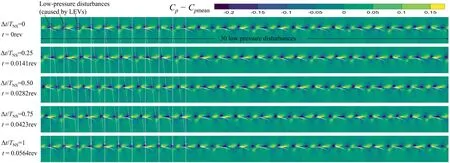
Fig. 14 Disturbed pressure coefficient Cp at blade-to-blade plane in one annulus for NS condition.

Fig. 15 Disturbed pressure coefficient Cp at blade-to-blade plane in one annulus for RS condition.
A detailed experimental and numerical study on non-bladeorder flow disturbances has been carried out on a research axial compressor rig with detailed time-resolved pressure measurement data. With the use of full-annulus unsteady simulations of the compressor, along with space–time correlation and spatial Fourier decomposition, the propagation and scale characteristics of non-blade-order disturbances around the compressor rotor were examined in details. Furthermore, a linkage between the origination mechanism of non-bladeorder disturbances and evolution behavior of the unsteady vortical flow structures has been established. The major conclusions are drawn as follows:
(1) Though the multiple frequency peaks in pressure spectra reflect the multi-scale nature of non-blade-order flow disturbances, the results of space–time correlation on disturbed pressure indicate that the non-blade-order disturbance has a major spatial mode within the flow range from its appearance to stall condition. The non-bladeorder disturbance initially occurs with a spatial mode of 35 (short-length-scale of less than one blade pitch)under NI condition, and then its spatial mode shifts to 30 and keeps constant across a wide flow range until it reduces to 25 under stall condition.
(2) The results of spatial Fourier decomposition show that the multiple frequency peaks of NBOD in pressure spectra are caused by the interaction of the short-scale disturbances with a low-amplitude, low-frequency and long-scale (with scale of circumference) disturbance,which results in disturbances with multiple scales of consecutive spatial modes, along with multiple frequency peaks in spectra.
(3) Two different vortical mechanisms both contribute to the origination of non-blade-order propagating disturbances—one is the non-synchronous oscillation of the tip leakage vortex, and the other is the occurrence and migration of the leading-edge radial vortex. Nonblade-order disturbances first appear when the fluctuation of tip clearance vortex occurs,while the compressor still operates far from the stall boundary.The phase shift of the oscillations of tip clearance vortex between adjacent passages leads to the circumferentially propagating disturbances. Leading-edge radial vortex generates under near stall condition, and its movement induces a circumferential propagating disturbance overlaying on the one caused by oscillating tip leakage vortex.
(4) As the compressor approaches to stall boundary, the propagating leading-edge vortexes are circumferential nonuniform scattered, which results in the dense and sparse distribution of leading-edge radial vortexes,leading to a high-amplitude long-scale (of circumference)disturbance, i.e. stall disturbance.
The authors declare that they have no known competing financial interests or personal relationships that could have appeared to influence the work reported in this paper.
The first four authors would like to acknowledge the support from National Natural Science Foundation of China (No.51906205).
推荐访问:blade order Nature